|
WWW.SPYSHOP2000.COM
The WTX-1
Wireless
Video Transmitter System
|
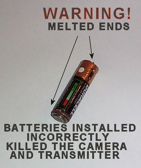
Warning!
Click on photo to enlarge picture.
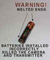
Installing
the batteries incorrectly will kill this system on the spot!
There are little pictures in the battery clip that show you how to
install each battery in each slot.
PAY ATTENTION!
All
systems are thoroughly tested before shipping.
There
are exposed electronics here. Do not let any of the components
touch one another! This will result in permanent damage to
transmitter.
BE
CAREFUL!
|
WTX-1
INSTRUCTIONS
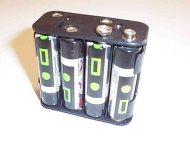
Install
8 new “AA” batteries in the battery clip while keeping the warning
at the top of this page in mind.
Make sure your putting the batteries just like the little pictures in
the clip say.
The power output cable from the battery clip connects to the power input
on the transmitter shown on the left side of the WTX-2 shown
below.
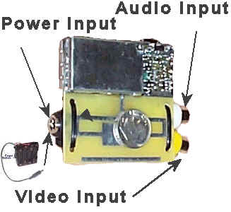
Connect the video source from your camera or video device to the Yellow
RCA connector shown on the right of the WTX-1 above. Also connect the
audio from your microphone to the white audio input shown above if you upgraded
to the WTX-2. If you have the WTX-1 there will not be a audio input.
RECEIVER CONNECTION
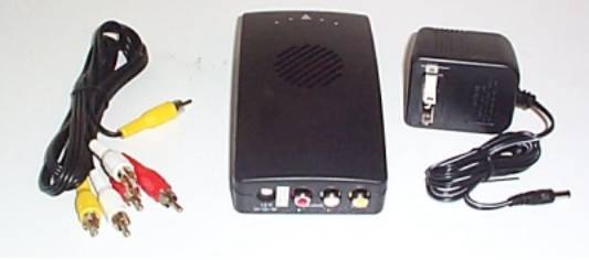
There are two different types of receiver units.
If you got the audio upgrade then your receiver unit will have a channel
selector on the side and audio outputs. This channel selector should be
set on channel one if this is your first unit that you purchased from
us.
Make sure the receiver is set to channel one unless otherwise
indicated by us.
If your system doesn’t have a channel selector then don’t worry
about this because you only have one preset channel.
99% of the support emails that we get are because the channel
selector is not on channel one.
Plug the power supply into the wall. Plug the other end into your
receiver. Move the power switch on the receiver to the “ON”
position. The red power light will come on. If the red light on the
receiver does not come on check the outlet that you have it plugged into
to make sure it has power. A light switch somewhere in the room may
control some outlets. If this is the case make sure the switch is on.
Put the channel selector on channel one.
Turn on the transmitter power.
The color-coded plugs are known as RCA type plugs.
The plugs
on the cable and the receiver unit are color coded to make this really
simple. Unfortunately not all manufactures follow the standard color
code. The video output of the receiver unit is labeled VIDEO. On your TV
or VCR there will be a VIDEO INPUT. You need to connect the video of the
receiver to the video input of your TV or VCR. If you got a system with
out audio the patch cord that you received might not be the same color
as the plug on the receiver. Simply ignore the color of the patch cord
and pay attention to the color of the video plug on the receiver and
your TV or VCR.
If you got a system with audio then your patch cord color will match the
colors of the plugs on the receiver.
Connect one end of the yellow patch cord to the video on the
receiver and the other end to the Video on your TV or VCR. The red and
white patch cords are for the audio. Connect one end of the red patch
cord to the receiver and the other end to your TV or VCR’s audio
input. Connect one end of the white patch cord to your receiver and the
other end to your TV or VCR’s other audio input. Some TV’s and
VCR’s only have one audio input. If this is the case on your TV or VCR
then leave the white patch cord unplugged on the TV/VCR end.
Connecting the receiver unit to your TV or VCR is really pretty easy.
Now
for the hard part…
Now that your receiver is connected to your TV or VCR we need to figure
out how to see the images coming from your camera. For testing purposes
it’s best to start by connecting the receiver to your TV and not to
your VCR. You might want to
get your TV manual out for this part.
In order to see the video coming from the camera we need to find out how
to select the video input source on your TV that we just got through
hooking the receiver unit to. To get to the video source on most TV’s
you keep pressing the channel down button until your one or two clicks
below channel one. Most TV’s will display “VIDEO 1” or VIDEO 2”
when you’re on the video input source.
Other TV’s will have a video source button on the remote or on the TV
itself. This button will usually be labeled “VIDEO 1” or VIDEO 2”.
This isn’t always the case. Some TV’s may use some other method of
getting to the video input source so you will defiantly need to get out
your manual for the TV and look for the section that covers connecting
external devices or a VCR to your TV.
Every one of these systems is tested right before they are put in the
box to ship to you so we know that they worked when we shipped them. In
most cases when we get a system back because someone thought the system
wasn’t working, it works when we get it. With that in mind you need to
be sure that you have tried everything before jumping to the conclusion
that the system is not operating properly.
Now that you have the system working and you can see the video on your
TV, lets get it working through your VCR. Follow the same steps used to
connect the receiver to your TV only now connect the receiver to your
VCR.
There are usually two ways to connect the VCR to your TV. You can either
use RCA patch cords like we use to connect the receiver to the TV or you
can use a coax cable. A coax cable is a cable that’s round and usually
screws on to the TV or VCR.
Connecting the VCR to the TV with RCA patch cords:
You will do this just like we did with the camera receiver. Connect the
RCA video output of the VCR to the RCA video input of the TV. The TV
should already be set to its video input because we just had it working
with the camera. Put videotape in the VCR and press play. You should see
the movie on the tape playing on the TV. Now you know that the TV is
receiving video from the VCR. Skip the next section on using coax to
connect your VCR to your TV.
Connecting the VCR to the TV with coax:
Screw
on end of the coax cable on the RF out of the VCR. Screw the other end
on to the RF in on your TV. Put videotape in the VCR and press play. Set
the TV to channel 3 or 4. You should see the movie that’s on the
videotape playing. Now you know that the TV is receiving video from the
VCR. You have to know this before we try to see the video from the
camera.
Now that we know how to see video from the VCR on the TV we
need to know how to see the camera video through the VCR. Just like your
TV the VCR has a way to select video from its external video input. Just
like your TV using the channel down button on the VCR usually does this.
The external video source is usually one or two clicks just below
channel one. Just like your TV the video input source of the VCR might
be selected by pressing a button on the VCR or its remote labeled
“VIDEO 1” or “VIDEO 2”. You may need to get out your VCR’s
manual to figure this out.
This is really far simpler that it might seem. Be patient. Read through
these instructions several times before giving up. The main thing it to
start with just the TV so you know that the system is working and with
that knowledge you will know that it’s just a matter of figuring out
how to get the video working through the VCR.
One you have the video working through the VCR to your TV you can
record the video on videotape and pay it back though the TV. If you
still need assistance you can find our contact information on our
website at www.spyshop2000.com
under the contact information link. Were her to help so feel free to let
us know if your having trouble. Again please make sure you have tried
everything before jumping to the conclusion that the system is not
working properly. This is extremely rare.
These are delicate systems. The most common cause of system failure is
caused be letting the camera or transmitter electronics come in contact
with each other or some other object that shorts out the system. If you
didn’t order the shrink-wrap option we strongly recommend that you
protect the system with electrical tape or some other method. If a
system fails due to shorting it’s obvious when tested. If this is the
case we will not repair or replace your system with out charge. Please
be extremely careful to prevent shorts. If you would like to purchase
the shrink-wrap option, you can send your system back to us and we will
add the shrink-wrap for you. All systems are tested upon arrival for
proper operation. If your system is not operational when we get it we
will immediately ship it back to you. You will need to pay for the
upgrade and return shipping before sending the unit to us.
You will need to obtain a return merchandise authorization number
before shipping the unit to us. Any package shipped to us must have this
RMA number or the system will be returned to sender and you will have
wasted shipping expenses.
The CCD camera on your system is consuming power. When power is consumed
heat is generated. Your camera will get very warm and sometimes hot
during operation. This is normal. This is not a malfunction.
The average battery operation time is 3 to 6 hours. If your needing to
operate the system for longer periods of time you can obtain a plug in
power supply for the transmitter and camera by contacting us at sales@spyshop2000.com
and we will give you the information you need to purchase what we call
the BUG PLUG. Attempting to make your own PUG PLUG could result in
reverse polarity, which is basically shorting out the system. If your
not absolutely confident that you have the skills to do this the please
don’t attempt to as it could get very expensive to correct your error.
If you already purchased the BUG PLUG from us the instruction on
how to use it are below.
ACCESSORIES
If you didn’t get the audio upgrade with your system at the time of
purchase you can upgrade at any time. This will require you sending your
system in. All systems are tested upon arrival for proper operation. If
your system is not operational when we get it we will immediately ship
it back to you. When doing an audio upgrade you will need to pay for the
upgrade and return shipping before sending the unit to us.
You will need to obtain a return merchandise authorization number
before shipping the unit to us. Any package shipped to us must have this
RMA number or the system will be returned to sender and you will have
wasted shipping expenses.
You can see the WTX-2 with audio capabilities at:
http://www.spyshop2000.com/Wireless_Transmitters.htm
Portable power for your receiver unit:
If you would like to
operate your receiver on batteries for portable operation you can
purchase a custom battery pack from us at http://www.spyshop2000.com/batteries.htm
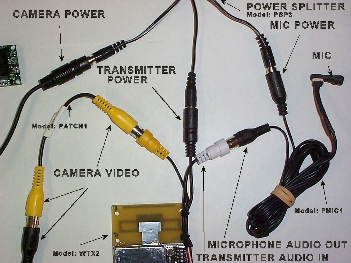
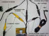
System
connections
Click on images to enlarge:
See
other accessories here

|